Give the SRP Calculator™ a try at www.unicous.com/oilgas/srpcalc.php and let us know what you think. We would appreciate any feedback that can make this tool more useful for you. Check future issues of Solutions or our Web site for enhancements to the SRP Calculator™ as well as other new artificial-lift design tools. You may also want to inquire about our artificial-lift drive systems that incorporate complete dynamic analysis, including dynamometer cards and gearbox torque plots.

|
|
||
|
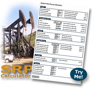
New sucker-rod pump calculator provides quick, easy analysis. |
||
|
|
||
|
Watch for these topics in upcoming issues. |
||
| Printer-Friendly Version | |
| Send to a Friend | |
| · Subscribe | |
| · Unsubscribe | |
![]()
| · Issue 7 (Apr. 2003) | |
| · Issue 6 (Mar. 2003) | |
| · Issue 5 (Feb. 2003) | |
| · Issue 4 (Dec. 2002) | |
| · Issue 3 (Nov. 2002) | |
| · Issue 2 (Nov. 2002) | |
| · Issue 1 (Oct. 2002) |
|
![]()
Oil & Gas Automation
Solutions is a publication
of Unico, Inc.
![]() Since 1967
Since 1967
Unico, Inc.
3725 Nicholson Rd.
P. O. Box 0505
Franksville, WI
53126-0505
262.886.5678
262.504.7396 fax
oilgas@unicous.com
unicous.com
Copyright © 2003
Unico, Inc.
All rights reserved.
All trade designations
are provided without
reference to the rights of
their respective owners.
New Sucker-Rod Pumping System Design Calculator Provides Free, Convenient Analysis On-Line
|
|
Parameter
|
API
Method RP 11L |
Unico
SRP Calculator™ |
Theta
Rodstar |
|
Pumping Speed
|
Constant speed
|
Constant speed
|
Allows variation
|
|
Fluid Level
|
Zero
|
Selectable
|
Selectable
|
|
Water Cut
|
None
|
Selectable
|
Selectable
|
|
Water Specific Gravity
|
None
|
Selectable
|
Selectable
|
|
Oil API Specific Gravity
|
Fixed
|
Selectable
|
Selectable
|
|
Fluid Inertia Effects
|
None
|
None
|
Selectable
|
|
Tubing Pressure
|
Zero
|
Selectable
|
Selectable
|
|
Casing Pressure
|
Zero
|
Selectable
|
Selectable
|
|
Pump Depth
|
Selectable
|
Selectable
|
Selectable
|
|
Plunger Diameter
|
Selectable
|
Selectable
|
Selectable
|
|
Pump Efficiency
|
100%
|
Selectable
|
Selectable
|
|
Pump Fill
|
100%
|
Selectable
|
Selectable
|
|
Tubing Size
|
Selectable
|
Selectable
|
Selectable
|
|
Tubing Anchor
|
Fixed
|
Selectable
|
Selectable
|
|
Stuffing Box Friction
|
Zero
|
Selectable
|
Selectable
|
|
Pump Friction
|
Zero
|
Selectable
|
Selectable
|
|
Pumping Unit Type
|
Class I
|
Class I or III
|
Class I or III
|
|
Rotation Direction
|
Fixed
|
Fixed
|
CW or CCW
|
|
Pumping Unit Stroke
|
Selectable
|
Selectable
|
Unit database
|
|
Unbalanced Force
|
Zero
|
Selectable
|
Unit database
|
|
Articulating Inertia
|
Zero
|
Zero
|
Unit database
|
|
Balance Moment
|
Ideal
|
Selectable
|
Selectable
|
|
Prime Mover Type
|
None
|
AC Motor
|
Selectable
|
|
Rod String Sections
|
Four
|
Three
|
Eight
|
|
Rod String Material
|
Steel
|
Steel
|
Steel or Fiberglass
|
|
Rod String Type
|
Continuous
|
Coupled or Corod
|
Rod database
|
|
Sinker Bars
|
None
|
None
|
Selectable
|
|
Buoyant Rod Load
|
Calculated
|
Calculated
|
Calculated
|
|
Fluid Column Load
|
Calculated
|
Calculated
|
Calculated
|
|
Maximum Rod Load
|
Calculated
|
Calculated
|
Calculated
|
|
Minimum Rod Load
|
Calculated
|
Calculated
|
Calculated
|
|
Required Balance
|
Calculated
|
Calculated
|
Calculated
|
|
Max. Gearbox Torque
|
Calculated
|
Calculated
|
Calculated
|
|
Polished Rod Power
|
Calculated
|
Calculated
|
Calculated
|
|
Fluid Production
|
Calculated
|
Calculated
|
Calculated
|
|
Dynamometer Card
|
None
|
None
|
Displayed
|
|
Gearbox Torque Plot
|
None
|
None
|
Displayed
|
The results of the SRP Calculator™, the Rodstar program, and the API RP 11L method are compared below for both Class I and Class III well examples. The relative error of most of the SRP Calculator™ calculations, which use some simplifying assumptions, is 10% or less, with many being within 5%. The only significant difference between the SRP Calculator™ and the Rodstar program occurs with the minimum motor size, for which the Unico program was able to select a smaller motor on the Class III pump. A number of results fall between those estimated by the Rodstar program and the API method. Additional care should be taken with values that fall to one side or another of both other methods. Generally, the SRP Calculator™ provides somewhat better results for Class I than Class III pumping units.
Analysis Comparison (Class I Example)
| Calculation |
Unico SRP Calculator
|
Theta
Rodstar |
Unico/
Rodstar |
API
|
Unico/
API |
| Fluid Production Rate (bpd) |
323
|
331
|
-2%
|
331
|
-2%
|
| Oil Production Rate (bpd) |
65
|
66
|
-2%
|
66
|
-2%
|
| Polished Rod Power (hp) |
26.1
|
27.7
|
-6%
|
21.4
|
+22%
|
| Minimum Motor Size (hp) |
60.0
|
60.0
|
0%
|
—
|
—
|
| Required Balance (in-lb) |
1,878,714
|
1,920,570
|
-2%
|
—
|
—
|
| Existing Balance Effect (lb) |
23,557
|
23,407
|
+1%
|
—
|
—
|
| Required Balance Effect (lb) |
22,129
|
22,418
|
-1%
|
21,706
|
+2%
|
| Max. Gearbox Torque (in-lb) |
977,751
|
1,007,000
|
-3%
|
753,406
|
+30%
|
| Buoyant Rod Load (lb) |
15,696
|
15,942
|
-2%
|
15,636
|
0%
|
| Maximum Rod Load (lb) |
30,716
|
31,266
|
-2%
|
28,007
|
+10%
|
| Minimum Rod Load (lb) |
10,541
|
10,446
|
+1%
|
10,389
|
+1%
|
| Tubing Stretch (in) |
1.07
|
1.10
|
-3%
|
1.10
|
-3%
|
| Pump Stroke (in) |
126.46
|
129.00
|
-2%
|
128.30
|
-1%
|
Analysis Comparison (Class III Example)
| Calculation |
Unico SRP Calculator
|
Theta
Rodstar |
Unico/
Rodstar |
API
|
Unico/
API |
| Fluid Production Rate (bpd) |
318
|
331
|
-4%
|
331
|
-4%
|
| Oil Production Rate (bpd) |
64
|
66
|
-4%
|
66
|
-4%
|
| Polished Rod Power (hp) |
25.6
|
27.9
|
-8%
|
21.4
|
+20%
|
| Minimum Motor Size (hp) |
50.0
|
60.0
|
-20%
|
—
|
—
|
| Required Balance (in-lb) |
2,087,616
|
2,175,160
|
-4%
|
—
|
—
|
| Existing Balance Effect (lb) |
21,958
|
21,197
|
+4%
|
—
|
—
|
| Required Balance Effect (lb) |
22,920
|
23,525
|
-3%
|
21,706
|
+6%
|
| Max. Gearbox Torque (in-lb) |
763,923
|
801,000
|
-5%
|
753,406
|
+1%
|
| Buoyant Rod Load (lb) |
15,695
|
15,941
|
-2%
|
15,636
|
0%
|
| Maximum Rod Load (lb) |
30,299
|
30,713
|
-1%
|
28,007
|
+8%
|
| Minimum Rod Load (lb) |
10,209
|
9,336
|
+9%
|
10,389
|
-2%
|
| Tubing Stretch (in) |
1.07
|
1.10
|
-3%
|
1.10
|
-3%
|
| Pump Stroke (in) |
124.53
|
129.00
|
-3%
|
128.30
|
-3%
|
In Future Issues...
Look for the following articles in upcoming issues of Oil & Gas Automation Solutions:
| Taking advantage of utility rate structures to reduce artificial-lift energy costs | |
| Unico drives plot and control pump fill using inferred downhole dynamometer graphs | |
| Power loss components in a typical rod pumping system | |
| A novel way of conceptualizing the effectiveness of artificial lifts | |
| Reducing power consumption and improving power factor of beam pumps | |
| Detecting PCP stick/slip oscillations that fatigue rod-string couplings and reduce energy efficiency | |
| Embedded well control is engineered for compatibility with Rotaflex® units |