|


Oil & Gas Automation
Solutions is a publication
of Unico, Inc.
 Since 1967 Since 1967
Unico, Inc.
3725 Nicholson Rd.
P. O. Box 0505
Franksville, WI
53126-0505
262.886.5678
262.504.7396 fax
oilgas@unicous.com
unicous.com
Copyright © 2002
Unico, Inc.
All rights reserved.
All trade designations
are provided without
reference to the rights of
their respective owners.
|
|

 The Subtle Effect of Crank Rotation Direction on Counterbalance with Class I Pumping Units The Subtle Effect of Crank Rotation Direction on Counterbalance with Class I Pumping Units
by Theresa Smigura development/system engineer
Unlike Class III Advanced Geometry Beam pumping units and Mark II pumping units, for which API specifications recommend that the crank arm rotate in the counterclockwise direction only, Class I Conventional rotary balanced units can operate in either direction. While seemingly a simple choice, the selection of rotation direction can have an adverse impact on the pumping unit and its costly gearbox.
The dynamometer graphs (rod load versus rod position) that are used everyday to diagnose many pumping-unit issues do not clearly show the subtle effect that the crank rotation direction has upon a Class I pumping unit. While a dynamometer graph does warn of exceeding the pumping unit’s rod load limitations, only a plot of crank torque can warn of overloading the pumping unit’s gearbox. Even more information becomes apparent with a plot of rod and pump velocities versus time.
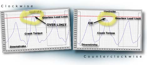
Selecting the wrong direction of crank rotation could overload the pump's gearbox.
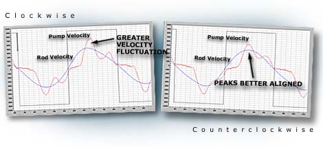
This pump accelerates more slowly and better follows rod velocity when rotating counterclockwise.
In this example, all well information was held constant except for the direction of crank rotation.
| Pump Cycle Time at 6 spm |
Counterclockwise |
Clockwise |
Optimum |
| Gearbox loading |
90% |
103% |
CCW |
| Peak gearbox torque |
578,000 in-lb |
657,000 in-lb |
CCW |
| Peak polished-rod load |
25,558 lb |
25,624 lb |
CCW |
| Gross pump stroke |
123 in |
121 in |
CCW |
| Maximum rod velocity (upstroke) |
45.8 in/s |
46.6 in/s |
CCW |
| Maximum pump velocity (upstroke) |
60.2 in/s |
69.4 in/s |
CCW |
| Maximum rod velocity (downstroke) |
46.6 in/s |
45.8 in/s |
CCW |
| Maximum pump velocity (downstroke) |
69.4 in/s |
60.2 in/s |
CCW |
| Pump movement (upstroke) |
75% of total time |
73% of total time |
CCW |
| Fluid production |
164 BFPD |
161 BFPD |
CCW |
The findings compiled in this table show that there is a clear choice of crank rotation that keeps the pumping unit operating within its structural limitations, allows it to produce slightly more fluid, and possibly adds a little life-expectancy to the rod string and pump due to slightly decreased stresses. Even though a Class I pumping unit has almost symmetrical up and down strokes, the length of the upstroke cycle time and the down-stroke cycle time are different. While evaluating the almost symmetrical torque signatures, the differences may seem minuscule, but they do have a subtle effect. Changing the pump direction causes the pumping unit to swap the upstroke action for the downstroke action, which, in this case, causes the upstroke cycle time to be slightly shorter than the downstroke time. In addition, the slightly slower upstroke speed can help reduce gas breakout. Given sufficient inflow, as the upstroke speed decreases, the pressure differential across the standing valve will also decrease, thereby increasing the pump fill and production rate. Since both dynamometer plots remain essentially identical, none of these benefits can be found while evaluating dynamometer graphs alone.
While not all cases may point as clearly towards a certain crank rotation direction, a best-practice procedure for evaluating the performance of any well should include producing a crank torque plot, a rod velocity plot, and a pump velocity plot while running the pumping unit (in both directions for a Class I). Even though most Class III and certainly all Mark II units should be run in the counterclockwise direction, these plots will help determine how to best protect the pumping unit, rod string, and pump.
For more information on the effects of crank rotation direction, please contact us.

Cost-Effective Enclosures Introduced for Hostile
Outdoor Environments
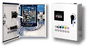 Unico has taken advantage of some of its drive-design features to introduce a line of cost-effective enclosures specifically intended for outdoor pumping applications. Competitors often punch holes in enclosures and add ventilating to cool their drives, thereby exposing sensitive electronic components to the elements. Unico drives are uniquely designed to allow the heat sink to extend through the wall of the enclosure while maintaining NEMA 4 (IP66) box integrity. The drive keypad/display and operator devices have NEMA 4 rating that enables them to be mounted on the door of the enclosure. Optional strip heaters and heat exchangers are available for extremely cold or hot environments. Rain and sun shields are also available to protect the system from extremes. A circuit breaker actuated by a through-the-door operator is suitable for use as service equipment (SUSE). Simply hook up the power, connect the electric motor, and you're ready to go. Unico has taken advantage of some of its drive-design features to introduce a line of cost-effective enclosures specifically intended for outdoor pumping applications. Competitors often punch holes in enclosures and add ventilating to cool their drives, thereby exposing sensitive electronic components to the elements. Unico drives are uniquely designed to allow the heat sink to extend through the wall of the enclosure while maintaining NEMA 4 (IP66) box integrity. The drive keypad/display and operator devices have NEMA 4 rating that enables them to be mounted on the door of the enclosure. Optional strip heaters and heat exchangers are available for extremely cold or hot environments. Rain and sun shields are also available to protect the system from extremes. A circuit breaker actuated by a through-the-door operator is suitable for use as service equipment (SUSE). Simply hook up the power, connect the electric motor, and you're ready to go.
 Contact us to learn more about packaging options. Contact us to learn more about packaging options.
 Go to top Go to top

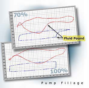
Sophisticated Drives Determine Pump Fillage without a
Load Cell
 Pump "fillage," a measure of how completely a sucker-rod pump is filled each stroke, is an important indicator of well operation. Typically, controllers estimate pump fillage either using power analysis or by interpreting dynamometer graphs—a preferable method that requires a load cell or strain gauge as well as a position transducer to generate the graphs. Unfortunately, load cells are prone to failure, are costly to install and maintain, and require periodic calibration. Pump "fillage," a measure of how completely a sucker-rod pump is filled each stroke, is an important indicator of well operation. Typically, controllers estimate pump fillage either using power analysis or by interpreting dynamometer graphs—a preferable method that requires a load cell or strain gauge as well as a position transducer to generate the graphs. Unfortunately, load cells are prone to failure, are costly to install and maintain, and require periodic calibration.
|
|
|
|
Three different methods of determining pump fillage provide flexibility in accommodating differing applications. The Torque method is used on pumping units having conventional geometry. Pump fillage is determined by analyzing the torque feedback and crank position signals within the
| Method |
Where Used |
How Determined |
| Torque |
Conventional beam pumps |
Calculated from torque feedback and
crank position |
| Rod Load |
Unconventional beam pumps and Rotaflex units |
Derived from internal real-time surface dynamometer graph |
| Pump Load |
Beam pumps with excessive rod dynamics |
Derived from internal real-time pump dynamometer graph |
drive. The Rod Load method, typically used with unconventional beam pumps and Rotaflex units, determines pump fillage by interpreting a real-time surface dynamometer graph. Fillage is derived from the calculated fluid pound position and calculated pump stroke. Where excessive rod dynamics make it difficult to interpret the surface dynamometer graph, the Pump Load method determines pump fillage by interpreting a real-time pump dynamometer graph based upon rod load, rod position, and an active model of the rod string and pump. Pump fillage is derived from the calculated fluid pound position and inferred pump stroke.
Of the three approaches, the Pump Load method can produce the most accurate estimate of fillage since it is completely independent of rod dynamics. The Torque method is the most robust because it does not need to know the API pumping unit or rod/pump parameters.
Determining pump fillage is only the first step to optimizing well production. The logical extension of measuring fillage is controlling it, which is the subject of the Technically Speaking column in our next issue.
Contact us to learn more about measuring pump fillage.

In Future Issues...
Look for the following articles in upcoming issues of Oil & Gas Automation Solutions:
 |
Controlling the pump fillage of a sucker-rod pump by modulating pumping speed |
|
Using drive torque limits to protect and extend the life of pumping unit gearboxes |
|
Unico 1100 Series drives offer 12-pulse operation for reduced harmonic currents |
|
A new benchmark for artificial lift energy efficiency |
Go to top
|
|
|

 Unico's sucker-rod pump drives employ a unique approach to determining pump fillage that eliminates the use of load cells by using internally generated dynamometer graphs. All measurements are made from motor torque, velocity, and position feedback signals derived from motor current and voltage. Crank position is calculated from motor position and gear ratio and is referenced once per stroke by an external switch. Rod