 A Benchmark for Assessing the Energy Efficiency of Artificial Lifts
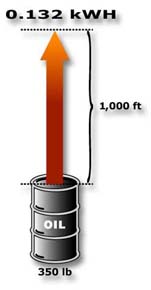 mark for comparing the energy efficiency of a broad variety of wells and artificial lift systems. In these situations, we can use the "perfect system" to create a such a benchmark.
![]() Contact us for help in measuring and improving the energy efficiency of your wells.
Contact us for help in measuring and improving the energy efficiency of your wells.

|
|
||
|
Benchmark allows you to compare the energy efficiency of various artificial lifts. |
||
|
|
||
|
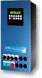
New packaging option saves space by integrating operator controls with the drive. |
||
|
|
||
|
Unique power-limiting feature boosts energy efficiency of beam pumps. |
||
|
|
||
|
Watch for these topics in upcoming issues. |
||
| Printer-Friendly Version | |
| Send to a Friend | |
| · Subscribe | |
| · Unsubscribe | |
![]()
| · Issue 5 (Feb. 2003) | |
| · Issue 4 (Dec. 2002) | |
| · Issue 3 (Nov. 2002) | |
| · Issue 2 (Nov. 2002) | |
| · Issue 1 (Oct. 2002) |
|
![]()
Oil & Gas Automation
Solutions is a publication
of Unico, Inc.
![]() Since 1967
Since 1967
Unico, Inc.
3725 Nicholson Rd.
P. O. Box 0505
Franksville, WI
53126-0505
262.886.5678
262.504.7396 fax
oilgas@unicous.com
unicous.com
Copyright © 2003
Unico, Inc.
All rights reserved.
All trade designations
are provided without
reference to the rights of
their respective owners.
|
A new packaging option for NEMA 1 drives provides similar space-saving simplicity for indoor applications by integrating |
|||||||||||||
|
the operator controls with the drive itself. Often this eliminates the need for a separate control station. As many as 12 operator devices can be mounted directly to the door of the drive enclosure in prepunched holes. Unused holes are sealed with removable plugs. Operator devices generally interface directly with the drive, which has provision for 12 digital inputs, six digital outputs, three analog inputs, and two analog outputs. Digital I/O can be either 24 V DC or 115 or 230 V AC/DC using plug-in converters. Analog I/O can be configured for 10 V DC or 20 mA operation. All digital and analog I/O points are completely programmable for specific applications using the IEC 1131-compliant programmable logic controller (PLC) resident within the drive.
|
|||||||||||||
|
|
|||||||||||||
|
motoring and regenerative portions of the cycle. If desired, dynamic braking losses can be eliminated completely by setting the regenerative limit to zero. Best of all, the feature does not affect the well's rate of production. Power limiting does come with a trade-off, however. Since rod velocity is less tightly regulated during power clipping, there is an increased potential for fluid pound, a condition that can damage pumping equipment. The Unico drive allows the user to determine the balance between system efficiency and equipment protection on a well-by-well basis. If optimal efficiency is the goal, power limiting can be used aggressively. If protecting the pumping unit is a greater concern, power limiting may be used sparingly to make power available for controlling pump velocity, rod load, bridle separation, and the like. Most applications run effectively somewhere in between.
If you'd like to learn more about saving energy with power limiting, please contact us. In Future Issues...Look for the following articles in upcoming issues of Oil & Gas Automation Solutions:
|
|||||||||||||
 Unico offers drives in three configurations—chassis units for mounting in customer-supplied enclosures, NEMA 1 (IP23) units for installation in controlled environments, such as power houses, and NEMA 4 (IP66) packaged units for outdoor environments. Packaged units combine the drive, circuit breaker, and other system components into a single enclosure together with optional door-mounted operator devices such as selector switches, push buttons, indicators, and potentiometers.
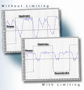 By nature, beam pumps have a cyclic power-usage profile that reflects their loading cycle. The power profile of a typical Class III pumping unit, for example, is comprised of two motoring peaks and two regenerative peaks per stroke. Unico's beam-pump software reduces the energy loss resulting from dynamic braking and peak motoring power excursions by clipping the peaks of the power cycle. The user can independently specify the degree of clipping for the
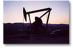 The charts above show the impact of power limiting on a well at Chevron-Texaco's Cymric site in southern California (right). Power and pump direction are shown before and after power limiting for a Mark II pumping unit running 6 spm on an 8,000-foot well. The speed modulations associated with power limiting reduced both the peak motoring power and the dynamic braking power, lowering the average input power from 40 hp to 34 hp. Pumping efficiency increased 10% from 66% to 76% while the overall pumping speed remained unchanged. Even greater efficiency gains were achievable, but these results represent the best compromise between system protection and power conservation for this well.