For more information on controlling pump fill, please contact us.
|
|
||
|
Improve energy efficiency and reduce equipment damage by regulating pump fill. |
||
|
|
||
|
Limit harmonic currents to 10% using Unico |
||
|
|
||
|
Torque-limiting feature extends the life of pumping unit gearboxes. |
||
|
|
||
|
Look for these topics in upcoming issues. |
||
| Printer-Friendly Version | |
| Send to a Friend | |
| · Subscribe | |
| · Unsubscribe | |
![]()
| · Issue 4 (Dec. 2002) | |
| · Issue 3 (Nov. 2002) | |
| · Issue 2 (Nov. 2002) | |
| · Issue 1 (Oct. 2002) |
![]()
Oil & Gas Automation
Solutions is a publication
of Unico, Inc.
![]() Since 1967
Since 1967
Unico, Inc.
3725 Nicholson Rd.
P. O. Box 0505
Franksville, WI
53126-0505
262.886.5678
262.504.7396 fax
oilgas@unicous.com
unicous.com
Copyright © 2003
Unico, Inc.
All rights reserved.
All trade designations
are provided without
reference to the rights of
their respective owners.
 Increase Pumping Efficiency by Controlling
Sucker-Rod Pump Fill
by Ron Peterson development engineer
 Incomplete pump fill is an undesirable and often unnecessary condition that diminishes the efficiency and longevity of sucker-rod pumping systems. A new method for modulating pumping speed to regulate pump fill improves energy efficiency while eliminating a major cause of equipment damage.
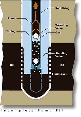
The fill of a sucker-rod pump is usually expressed as a percentage of full-pump capacity. Incomplete fill (less than 100%) is commonly caused by an insufficient fluid level in the well casing. Once fluid is depleted to the level of the pump, the pump begins drawing gas instead, as shown above. Another cause of incomplete fill is gas breakout during the pump upstroke. This occurs when a pressure drop across the standing valve releases dissolved gas from the fluid.
A pump operating with incomplete fill is inherently inefficient and may exhibit fluid pound, a destructive condition that leads to premature component failure. One method of preventing these conditions is to use a dedicated rod-pump controller (RPC). The RPC will stop the pump periodically to allow the well casing to fill, thus preventing a partially filled pump condition. While the RPC is an effective way to achieve better pump fill, it is prone to sand infiltration during standstill and eventual equipment damage from stopping and starting repetitively.
A preferable method of controlling pump fill is to modulate the speed of the pumping unit to maintain a target fill value. This keeps the fluid level at the top of the pump while minimizing gas breakout. With such a scheme, the pumping unit never completely stops. Upstroke and downstroke speeds are controlled independently. A lower upstroke speed reduces the viscous drag load, thus reducing viscous power consumption while allowing the pump to fill more slowly. In some cases, a lower upstroke speed assists gas separator functionality. It will also reduce the pressure drop across the standing valve, resulting in less gas breakout while filling by allowing more fluid to enter the pump. A higher downstroke speed increases the average overall speed and potentially alleviates gas locking by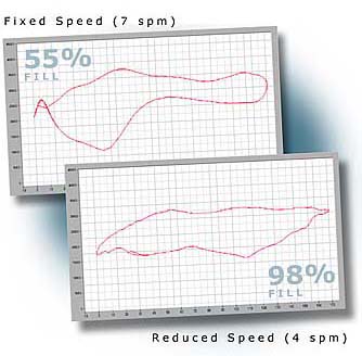 increasing the pressure differential across the traveling valve. Downstroke speed, however, is limited to prevent rod buckling and bridle separation.
The surface dynamometer graph (rod load versus rod position) shown at top right illustrates a pump running at a fixed speed of 7 spm with 55% fill; its output flow is 180 BPD, while the average input power is 30 hp. The bottom chart shows the same pump running at a reduced average speed of 4 spm (with 98% pump fill); its output flow is maintained at 180 BPD, while the average input power is reduced to 20 hp. By reducing pumping speed to control pump fill, the peak rod load is reduced, minimum rod load is increased, and fluid pound is eliminated. In addition, pumping efficiency is improved by reducing the average power consumption per stroke.
Satisfy Utility Requirements and IEEE 519 Harmonic Guidelines Using 12-Pulse 1100 Series Drives
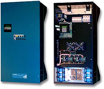 Unico's 150 to 500 hp 1100 Series drives now provide an optional input connection for six-phase (12-pulse) operation to help installations meet increasingly stringent power-quality requirements. The units incorporate link chokes that limit harmonic current to about 30% using a three-phase power source. When connected to a six-phase source, harmonic currents are further lowered to about 10%. The 1100 can be mounted with its heat sink extending through the wall of a NEMA 4 (IP66) enclosure for use in hostile or outdoor environments. Control electronics are maintained in a sealed environment while allowing heat to be dissipated outside of the enclosure. Drives also have provision for up to 12 optional operator devices, such as potentiometers, selectors, push buttons, and indicators, that can be configured to meet unique customer requirements. The drives, when combined with Unico's application software, are ideally suited for high-power ESP and PCP applications.
To learn more about the 1100 Series or eliminating harmonic currents, please contact us.
Protect and Extend the Life of Pumping Unit Gearboxes with Drive Torque Limits
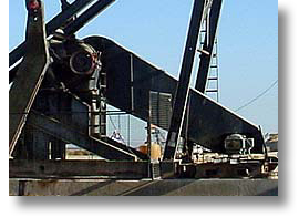 When a motor is operated directly across the line, there is no way to limit the amount of torque it delivers. Consequently, without a drive, your pumping unit's expensive gearbox is unprotected. While all Unico drives provide a means of limiting their torque output, our beam pump/Rotaflex application software goes a step further with a unique feature specifically designed to protect the gearbox.
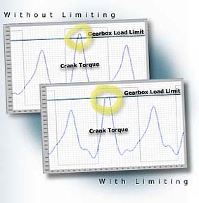 Using basic information about the pumping system, the gearbox limiting feature reduces the maximum allowable torque limit as necessary to ensure that the gearbox is never overtorqued. Protecting the gearbox from excessive torque extends its life expectancy.
Perhaps the best part of this feature is that it works automatically. During start-up, the software calculates the overall gear ratio between the motor and ![]() gearbox. Then, given the rated torque of the gearbox, together with a user-adjustable torque limit, the software determines whether the drive and motor are capable of delivering more torque than the gearbox can handle. If so, the drive’s torque limit is reduced to a safe level. A true/false parameter informs you whether or not gearbox limiting is in effect.
gearbox. Then, given the rated torque of the gearbox, together with a user-adjustable torque limit, the software determines whether the drive and motor are capable of delivering more torque than the gearbox can handle. If so, the drive’s torque limit is reduced to a safe level. A true/false parameter informs you whether or not gearbox limiting is in effect.
Gearbox limiting is just one of many features we've engineered to keep your wells productive. For more information, please contact us.
In Future Issues...
Look for the following articles in upcoming issues of Oil & Gas Automation Solutions:
| A useful benchmark for artificial lift energy efficiency | |
| Space-saving option integrates operator devices and drive | |
| Capturing and displaying rod-pump dynamometer graphs with a Palm Pilot | |
| Conceptualizing the effectiveness of artificial lift systems | |
| Taking advantage of utility rate structures to reduce artificial lift energy costs | |
| Power loss components of a typical rod pumping system |