TECHNICALLY SPEAKING:
 Controlling Harmonics with Variable-Speed Artificial Lift Drives Controlling Harmonics with Variable-Speed Artificial Lift Drives
by Bill Hammel vice president, engineering
At the 2005 ESP Workshop, held April 28-29 in Houston, there were six papers that referenced the problems of power-line harmonics due to the variable-speed drives (VSDs) used to control ESPs. Three of those papers (Field Comparison of Adjustable Speed Drive Technologies for Use on Submersible Pumps by Turner, LeDoux, and Salmas; Surface Electrical Reliability and Efficiency Improvements in Cravo Norte by Morales and Gomez; and ESP Power Quality Check: Field Case Study by Gohary, Al-Bimani, Al-Mahrouqi, Al-Busaidy, Ellithy, and Metwally) dealt almost exclusively with power-quality issues.
The following information on the various methods of controlling electrical harmonics may be useful to users of VSDs for operation of their artificial lift pumps.
Variable-Speed Drive Types
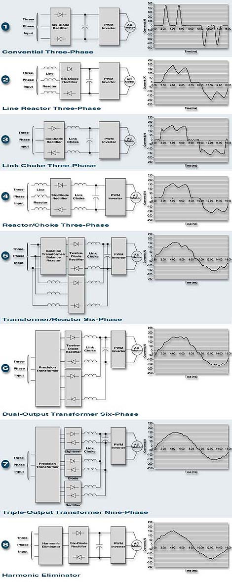
AC drives are generally based on pulse-width modulation (PWM) of a DC bus voltage to control the flow of power to an AC motor. The source of this DC bus voltage is generally a three-phase (six-pulse) rectifier (see Figure 1).
Power line quality can be improved by the addition of a line reactor to smooth the input current (Figure 2), a link choke to filter the rectifier output to the DC bus (Figure 3), or both (Figure 4). Further improvement can be made by the use of an isolation transformer, balancing line reactor, and additional bridge rectifier to operate in a six-phase (12-pulse) configuration (Figure 5).
Transformers can be precision wound to provide six-phase (12-pulse) or nine-phase (18-pulse) operation (Figure 6 and Figure 7). A harmonic eliminator can be used to provide nearly complete cancellation of harmonic current (Figure 8) similar to that achieved with 18-pulse systems.
Power Quality
Power line quality can be defined in terms of power factor and harmonic currents.
Power Factors
Total power factor is made up of both displacement and distortion components. Displacement power factor is the phase shift between line voltage and current. With a displacement power factor of unity, the current is exactly in phase with the voltage and the transfer of power is optimal. On the other hand, at zero power factor, no power is delivered even though there may be large circulating currents in the power line.
Harmonics
Harmonic currents are those that deviate from a pure sine wave and are generally expressed as a percentage of the fundamental current or as a distortion power factor. The percentage of harmonic current is generally referred to as Total Harmonic Distortion (THD).
High harmonic currents cause unfavorable distortion power factor, poor energy efficiency, and voltage distortion that may affect other equipment. An ideal system would have unity power factor and zero harmonic currents.
Power Quality Test Summary
|
|
|
|
|
|
|
D r i v e D e s i g n
|
Figure
|
Current
|
P o w e r F a c t o r s
|
|
|
|
THD
|
Displacement
|
Distortion
|
Combined
|
| Conventional three-phase (six-pulse) |
1
|
118.4%
|
1.00
|
0.64
|
0.64
|
| Line reactor three-phase (six-pulse) |
2
|
29.1%
|
0.97
|
0.96
|
0.93
|
| Link choke three-phase (six-pulse) |
3
|
31.3%
|
1.00
|
0.96
|
0.96
|
| Reactor/choke three-phase (six-pulse) |
4
|
23.8%
|
0.97
|
0.97
|
0.94
|
| Transformer/reactor six-phase (12-pulse) |
5
|
11.0%
|
0.98
|
0.99
|
0.97
|
| Dual-output transformer six-phase (12-pulse) |
6
|
7.8%
|
0.94
|
1.00
|
0.94
|
| Triple-output transformer nine-phase (18-pulse) |
7
|
4.3%
|
0.97
|
1.00
|
0.97
|
| Harmonic eliminator |
8
|
6.3%
|
1.00
|
0.99
|
0.99
|
|
|
|
|
|
|
Summary
The amounts by which actual systems deviate from this ideal standard are summarized in the above table for drives of various types operating at full load and full speed. Figures 1 through 8 show harmonic test results for various types of 100 hp PWM drive configurations.
Do you have questions about this article? If so, please contact us.
PERFORMANCE ANALYSIS TOOL:
On-Line Correlations Calculator Updated
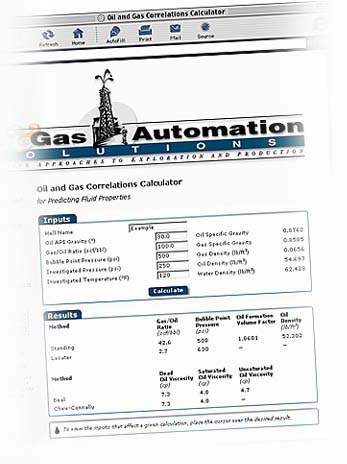
In the last issue of Solutions, Unico debuted its Correlations Calculator, a convenient tool for predicting the fluid properties of a well from limited information. The calculator implements published statistical relationships that estimate gas content and viscosity based upon field measurements. We introduced the first two correlations, the Standing and Beal methods. In this issue, we'd like to present two new ones, the Lasater and Chew-Connally methods.
 Lasater Correlation Lasater Correlation
In 1958, J. A. Lasater developed a correlation for assessing gas content based upon 158 samples having the following range:
Bubble-point pressures:
48 to 5,780 psia
Reservoir temperature:
82° to 272° F
Gas/oil ratio: 3 to 2,905 scf/STB
API: 17.9° to 51.1°
Gas gravity: 0.574 to 1.223
The method was originally presented graphically using two charts, but equations were later fit to extend its usefulness.
The Lasater correlation determines gas/oil ratio from the oil API gravity and investigated pressure and temperature. Bubble-point pressure is estimated based upon the API gravity, gas/oil ratio, and investigated temperature. The method does not determine the oil formation volume factor or oil density.
Lasater's method is slightly more accurate in predicting bubble-point pressure than Standing's when each is applied to its original data set. Lasaster's agreed within 3.8% as compared to 4.8% with the Standing method.
Chew-Connally Correlation
J. Chew and C. A. Connally introduced their correlation for determining the viscosity of gas-saturated crude oils in 1959. The effect of dissolved gas is to lighten the oil and decrease its viscosity. Their study data was taken from wells in North and South America.
The Chew-Connally correlation estimates dead oil viscosity using the oil API gravity, gas/oil ratio, and investigated temperature. Saturated oil viscosity is based upon the dead oil viscosity and adjusted for the gas content using the gas/oil ratio. Gas/oil ratio can be estimated using a correlation such as Standing's or Lasater's. The method does not determine the unsaturated oil viscosity.
Try these and other methods for yourself using the Correlations Calculator at www.unicous.com/oilgas/corrcalc.php. We will update the calculator as new methods are introduced in future issues of Solutions.
For more information, please contact us.
WHAT'S COMING UP:
In Future Issues...
Look for the following articles in upcoming issues of Oil & Gas Automation Solutions:
 |
Field tests of methods to eliminate rod pump gas locking and interference |
|
Reducing power consumption and improving power factor of beam pumps |
|
Using a torque economizer mode to improve efficiency and reduce gearbox stress |
|
Detecting stick/slip oscillations that fatigue rod-string couplings and reduce energy efficiency of PCPs |
|
Control options to ride through power disturbances |
Oil & Gas Automation Solutions is a publication of Unico, Inc. Copyright © 2005 Unico, Inc. All rights reserved.
All trade designations are provided without reference to the rights of their respective owners.
 Unico, Inc., 3725 Nicholson Rd., P. O. Box 0505, Franksville, WI 53126-0505 Unico, Inc., 3725 Nicholson Rd., P. O. Box 0505, Franksville, WI 53126-0505
262.886.5678 / 262.504.7396 fax
oilgas@unicous.com / unicous.com
|